Field Winding Dc Motor Series Motor Is
Armature Resistance control method for DC series motor. Speed control of DC series motor is done by the armature control and field control methods. Speed Control of DC Series Motor.
The production of magnetic flux in the device by circulating current in the field winding is called excitation.Many modern DC machines are constructed with a permanent magnet (PM) field, which results in a constant flux. Series motor is usually provided with thick wire, Options are (A) to provide large flux, (B) to reduce the use of insulating materials, (C) as it carries large load current, (D) in order to reduce eddy current, (E) , Leave The magnetic flux in a d.c machine is produced by field coils carrying current. The circuit diagram of this method is as shown in the below figure.Question is Field winding of a D.C.

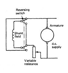
In addition, many motors are using permanent magnet fields. The motor design is referenced by the method these two components are wired together. The field windings and armature of the DC motor can be wired in various ways.
Machines is the machine in which field coils are connected in parallel with the armature. Generator, (b) Separately excited D.C. Machines are given in the figure.Figure: (a) Separately excited D.C. The connections showing the separately excited D.C. Source is used to energize the field coils it is called as separately excited D.C.

Generator (b) Long-shunt D.C. Motor.Figure: (a) Long-shunt D.C. Generator (b) Short-shunt compound D.C. If the shunt field is connected in parallel with the armature alone, the machine is called the short-shunt compound machine and if the shunt field in parallel with both the armature and series field, the machine is called the long-shunt compound machine.Figure: (a) Short-shunt compound D.C. The series winding has few turns of large cross-sectional area, and the shunt windings have many turns of fine wire.It can be connected in two ways.
The expression for both the conditions of operation is same.The clockwise current produces downward field, and anticlockwise current generates the upward field.Z = Total number of the conductor in the armature.A =No. Of rotation is known as back e.m.f., and E r = E b. Of rotation is called the generated e.m.f and E r = E g.In the case of the motor, the e.m.f. In case of a generator, the e.m.f.
Equation 2Mechanical power input = electrical power developedThe above equation is the torque equation for the D.C. Equation 1T is the electromagnetic torque developed by the motor running at n r.p.s.Electrical power developed = E x I a. So, the flux cut by one conductor in one revolution = фPE.M.F generated in each parallel path which is connected across a pair of carbon brushes.Mechanical power input = ωT.


 0 kommentar(er)
